Si/C Anode Materials
May 06,2025
D50:
6.0±1.0
Tap D g/cm³:
1.20±0.10
(Cap)mAh/g:
1680±50
(ICE)%:
77.0±1.0
Application:
Mid-Range Smartphone & Drone Battery / UAV Battery & Entry-Level Electric Vehicle (EV)
Si/C anode materials
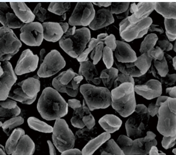
Silicon-carbon anode materials are composed of nano-scale silicon particles (Si, 20-200nm) compounded with carbon matrices (graphite/CNTs/graphene). Based on production processes, they are categorized into two technical routes:
Ball-Milling Method
- Process:
Si+C forms Si/C composite via high−energy ball milling
-Particle size: D50 <500nm
-Silicon content: 5-15wt%
-Conductivity: 10-100 S/cm
- Advantages
-Low cost (~¥80,000/ton)
-Simple process (compatible with existing graphite production lines)
- Challenges:
-High volume expansion (~300%)
-Limited cycle life (500-600 cycles @80% capacity retention
Nanosizing
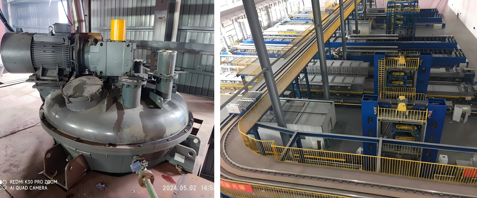
- During grinding, the rotor and zirconia beads generate intense impact forces (F=ma) and shear forces (τ=μdydv) through high-speed rotation effectively pulverizing and dispersing the Si/C anode material. The collisions and friction between zirconia beads (0.03-0.1 mm diameter) and Si/C particles progressively reduce particle size to D50 <100 nm while ensuring uniform dispersion in the liquid medium.As grinding proceeds, internal temperature rises (ΔT ≈15-25°C above ambient), necessitating real-time cooling via a dynamic cooling system to maintain temperature below 40°C. This is critical to:
1.Preserve material properties (e.g., prevent pitch degradation)
2.Ensure stable operation (avoid thermal expansion-induced equipment stress).
- The system monitors temperature through embedded sensors (accuracy ±0.5°C) and adjusts coolant flow (e.g., 10-20 L/min) automatically. After achieving target particle size (verified by laser diffraction), the homogenized slurry is discharged through the outlet valve for subsequent carbonization

Spray Drying( (ball milled Si/C)
- During grinding, the rotor and zirconia beads generate intense impact forces (F=ma) and shear forces (τ=μdydv) through high-speed rotation effectively pulverizing and dispersing the Si/C anode material. The collisions and friction between zirconia beads (0.03-0.1 mm diameter) and Si/C particles progressively reduce particle size to D50 <100 nm while ensuring uniform dispersion in the liquid medium.As grinding proceeds, internal temperature rises (ΔT ≈15-25°C above ambient), necessitating real-time cooling via a dynamic cooling system to maintain temperature below 40°C. This is critical to:
1.Preserve material properties (e.g., prevent pitch degradation)
2.Ensure stable operation (avoid thermal expansion-induced equipment stress).
- The system monitors temperature through embedded sensors (accuracy ±0.5°C) and adjusts coolant flow (e.g., 10-20 L/min) automatically. After achieving target particle size (verified by laser diffraction), the homogenized slurry is discharged through the outlet valve for subsequent carbonization

Carbonization
Carbonization: graphitized artificial graphite or natural graphite is uniformly mixed with pitch (pre-crushed to a specific particle size using specialized equipment) at a defined ratio in a high-speed mixer. The mixture is then transferred to a nitrogen-protected kiln for high-temperature carbonization at 1,200°C, where the pitch undergoes pyrolysis to form a carbon coating on the graphite surface.


Chemical Vapor Deposition (CVD) Method
- Process:
SiH4(g) deposits on porous carbon to form Si@C core
−shell structure
-Silicon layer thickness: 5
-20nm -Porosity: 30-50% -ICE: 85-89%
- Advantages:
-Superior performance:Capacity: 1,500-2,000 mAh/g
-Expansion rate: <100%
-Cycle life: 1,000+ cycles
- Challenges:
-High equipment cost (CVD reactors ~¥2M/unit)
-Silicon precursor cost (SiH₄: ¥50,000-100,000/ton in 2025)
Fluidized Bed
A fluidized bed reactor suspends silicon/carbon particles in a high-velocity gas stream (e.g., N2 or Ar), enabling uniform chemical vapor deposition (CVD) of silicon from precursors like silane (SiH4) and carbon coating from acetylene (C2H2)
1. Fluidization: Porous carbon powder (D50: 10–50μm) is fluidized via gas distribution plates (velocity: 0.1–1 m/s).
2. Silicon Deposition: SiH4 decomposes at 500–800°C, forming nano-silicon (5–20nm) within carbon pores
3. Carbon Coating: Secondary C2H2 cracking at 700–1000°C creates 2–5nm conductive carbon layers.

Previous
Next
Previous:
Next:
MORE PROJECTS

Natural Graphite Anode Material


